
Welcome to the first blog on The CAE Lab! If you’re new to Computer-Aided Engineering (CAE), you’re in the right place. This post introduces the essential terms and stages of CAE in simple, beginner-friendly language, using examples like analyzing a bike frame or a car part. Whether you’re curious about simulations or exploring our tutorials and portfolio, this guide will help you get started. Let’s dive into the world of CAE!
What is CAE?
Before we explore the stages and terms, let’s cover the basics of CAE and its core methods.
-
Computer-Aided Engineering (CAE) – CAE uses computer software to simulate how designs, like a car part or a bridge, behave under real-world conditions such as stress, heat, or fluid flow. It helps engineers test and improve designs virtually, saving time and cost compared to building physical prototypes.
-
Finite Element Method (FEM) – FEM is the math behind breaking a complex object, like a bike frame, into tiny pieces to study how it behaves under forces, heat, or pressure. Think of it like slicing a cake to analyze each piece, it makes solving complicated engineering problems easier and faster.
-
Finite Element Analysis (FEA) – FEA is the process of using FEM in CAE software to simulate how a part, like an airplane wing, handles stress, heat, or other conditions. It’s a key tool in CAE, letting engineers predict and improve a design’s performance before building it.
The Three Stages of CAE Analysis
Every CAE simulation, whether it’s FEA, Computational Fluid Dynamics (CFD) for fluids, or another method, follows three main stages:
-
Preprocessing – Preprocessing is the preparation phase, like gathering ingredients before cooking. You define the geometry (the shape of your object, like a bike frame), assign materials (e.g., steel or aluminium), set boundary conditions (how the object is fixed, like a bolted joint), and apply loads (forces, like a rider’s weight). This step ensures accurate inputs for reliable results.
-
Solving – Solving is where the software does the heavy lifting. The model is divided into smaller pieces (like puzzle pieces, called elements), and the solver uses math to calculate responses, like stress or deformation in the bike frame. This step can take seconds or hours, depending on the model’s complexity, and produces raw data for analysis.
-
Postprocessing – Postprocessing turns raw data into visuals, like color-coded maps showing stress or animations of deformation. Engineers use this to check if the design works, like ensuring the bike frame is strong enough. It helps answer questions like, “Is the structure safe?” or “Does it meet design goals?”
Core CAE Terminologies
Now that you understand CAE and its stages, let’s explore the key terms you’ll encounter, grouped for clarity.
Mesh Basics
The mesh is the foundation of a CAE model, breaking the geometry into smaller parts for analysis.
-
Mesh – The mesh is like a fishing net that divides the model’s geometry into smaller pieces (elements and nodes). A finer mesh, with smaller pieces, gives more accurate results but needs more computer power. It determines how closely the simulation matches the real world.
-
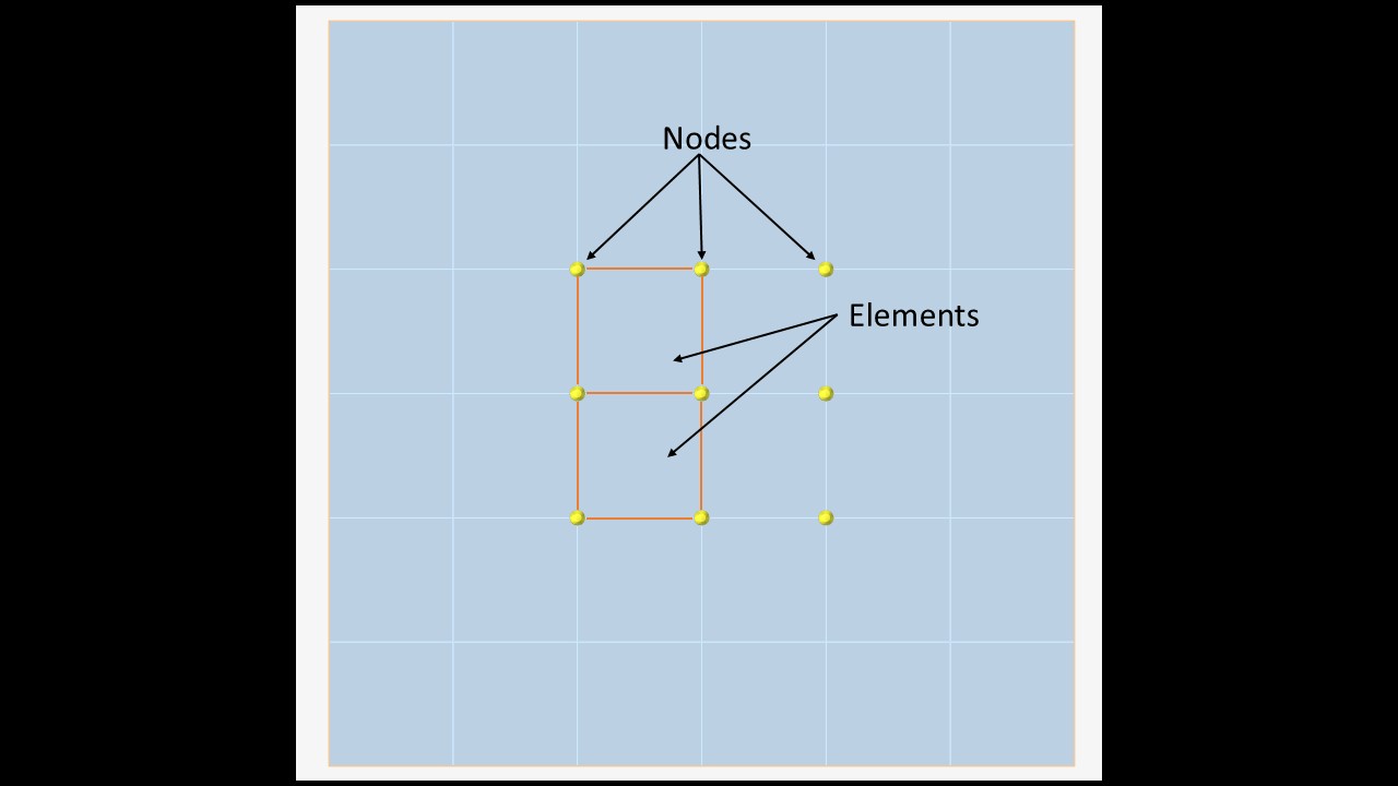
Nodes – Nodes are like the dots in a connect-the-dots drawing, forming the points where the mesh’s building blocks (elements) meet. In a 2D or 3D model, nodes are where the software calculates results, like how much a bike frame moves or experiences stress.
-
Elements – Elements are the building blocks of a mesh, connecting nodes to form the model’s structure. Think of them as puzzle pieces shaping a car frame or bridge. They come in types: 1D elements (like beams for bridges), 2D elements (like shells for thin panels), and 3D elements (like solids for bulky parts).
Model Setup
These terms define the model’s shape, materials, and behaviour.
-
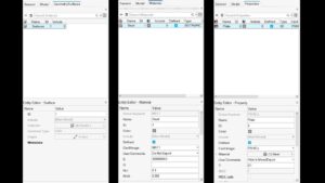
Geometry – Geometry is the shape and size of the object you’re analyzing, like a gear or a bike frame. It can be a single part or a group of parts, setting the foundation for the mesh.
-
Material – Materials define what your model is made of, like steel, aluminium, or rubber. Each material has properties, like stiffness, strength, or weight, which affect how the model behaves under forces.
-
Property – Properties are settings assigned to elements, like thickness for a thin panel or the type of element (e.g., beam or shell). They include material properties and other characteristics that define element behaviour.
Simulation Inputs
These terms describe the forces and constraints applied to the model.
-
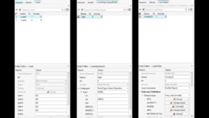
Load – Loads are external forces or conditions, like wind pushing on a skyscraper or heat in an engine. They drive the model’s deformation and stress, mimicking real-world conditions.
-
Boundary Conditions – Boundary conditions define how a model is held in place, like fixing a board to a wall. Examples include fixed supports (no movement) or pinned supports (can rotate but not move), which limit how the structure responds to loads.
-
Connection – Connections are how parts are joined, like bolts linking two plates or welds in a frame. In simulations, they define how forces and movements pass between components.
-
Load Step – A load step is a phase in a simulation where specific loads or conditions, like increasing pressure or changing temperature, are applied. Load step inputs define how these conditions change over time, simulating different scenarios.
Analysis Outputs
These terms describe the results engineers analyze after a simulation.
-
Stress – Stress is the internal resistance of a material to external forces, like pressure on a bike frame.
-
Strain – Strain is the deformation caused by those forces, like how much the frame stretches or compresses.
These are key outputs in FEA, showing where a design might fail.
Analysis Types
CAE simulations vary based on the problem being studied.
-
Types of Analysis – CAE analyses come in two main types:
-
Static Analysis: Examines how a structure behaves under steady loads, like weight on a bridge. It calculates displacement, stress, or strain in a stable state.
-
Dynamic Analysis: Studies changing loads, like vibrations in an engine or a car hitting a bump. It accounts for motion and time-varying forces.
-
Ensuring Accuracy
These terms focus on making simulations reliable and trustworthy.
-
Convergence – Convergence refers to how closely a simulation’s results match the true behaviour as the mesh is refined or settings are adjusted. A simulation “converges” when further refinements yield negligible changes, like stable stress results for a bridge model.
-
Validation and Verification – Verification ensures the simulation is set up correctly (e.g., the math and model are accurate), while validation checks if the results match real-world behaviour, like comparing a car part’s FEA results to a crash test. These steps build confidence in simulation outcomes.
Advanced Concepts
These terms dive deeper into CAE’s technical side.
-
Degrees of Freedom (DOF) – Degrees of freedom describe the ways a node can move. Think of a hinge that rotates in one direction—it has one DOF. In a 3D model, each node can move in three directions (x, y, z) and rotate around three axes, giving six DOFs. More DOFs mean more complex calculations.
-
Card Image – A card image is a text-based set of instructions that tells the CAE software how to set up the model, like defining materials or loads. It’s used in older or specialized solvers, while modern tools often use graphical interfaces.
Stay tuned for more tutorials on thecaelab.com, where we’ll explore CAE tools and share portfolio projects to inspire you. Have you tried a CAE simulation yet? Share your thoughts in the comments, or let us know what you’d like to learn next!